Product Center
———
High and Low Voltage Switchgear
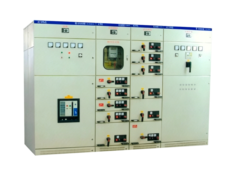
Low Voltage Panel AT-MNS
Professional power equipment from Suzhou Antai Transformer Co., Ltd.
Product Introduction
AT-MNS low-voltage withdrawable switchgear is suitable for three-phase AC 50/60Hz power systems with rated voltage 660V and rated current up to 4000A in three-phase four-wire and three-phase five-wire configurations, for receiving and distributing electrical energy. It is widely used in power plants, substations, industrial enterprises and high-rise buildings as Power Centers (PC) and Motor Control Centers (MCC).
This product complies with GB 7251.1-97, ZBK36001-89 and IEC 439-1 (1992) standards.
Model Designation

Features
1. Ambient air temperature not exceeding +40°C and not below -5°C; 24-hour average not exceeding +35°C.
2. Relative humidity not exceeding 50% at maximum temperature 40°C; higher relative humidity permitted at lower temperatures (e.g. 90% at 20°C), with occasional moderate condensation due to temperature variation.
3. Indoor use; altitude at installation site not exceeding 2000m.
4. Installation where severe vibration, shock or corrosive conditions affecting components will not occur.
Technical Parameters
The basic switchgear frame uses modular bolted assembly constructed from KB section steel joined with Grade 8.8 self-locking screws. Doors, panels, partitions, mounting brackets, busbars and functional units are added as required to form a complete switchgear assembly. Internal structural parts are galvanized and installed on a modular basis (modular pitch E=25mm). Panels are formed from 2mm high-quality steel on CNC equipment, acid-washed, phosphated and electrostatically powder-coated for wear and corrosion resistance, providing both mechanical strength and reliable earthing continuity.
Switchgear compartments include functional unit room, busbar room and cable room. Each area is strictly separated by continuously earthed metal plates or flame-retardant functional barriers to ensure safety and prevent fault propagation.
Horizontal busbars are flat-mounted to reduce electrical and thermal stress. Busbar cross-sections include 2(10×30), 2(10×60), 2(10×80) and 4(10×60) for rated currents 1250A, 2000A, 2500A and 4000A respectively; neutral (N) and protective earth (PE) busbars are 10×60. Vertical drawer busbars are 50×30×5 angle copper; all busbars are tin-plated.
MCC drawer sizes include 8E/4, 8E/2, 8E, 16E and 24E (E=25mm). Drawers have connected, test, disconnected, moving and isolated positions. Mechanical interlocking with switches ensures drawers can only be inserted or withdrawn when the switch is open; drawers cannot be moved when the switch is closed. Padlocks can lock switches in the open position. Identical functional unit drawers are interchangeable; each drawer provides 20 pairs of auxiliary contacts for remote control, metering and automated monitoring systems.
Installation & Operation
1. Install the product according to standard switchgear installation methods. Base channel steel and mounting bolts are supplied by the user. When connecting main busbars, ensure contact surfaces are flat and aligned; loosen cabinet bolts and readjust if necessary.
Product Documentation
The manufacturer shall supply the following documents and accessories:
a. Delivery list;
b. Certificate of conformity;
c. Product catalog;
d. Factory inspection report;
e. Primary system diagram, control schematic and secondary wiring diagram;
f. Door keys, operating handles and spare parts as specified in the contract;
g. Operation manuals for main components.
Ordering Information
The following information shall be provided when ordering:
a. Main circuit rated voltage and rated current;
b. Main circuit name and wiring principle;
c. Floor layout of the switchgear room;
d. Incoming and outgoing cable connection requirements;
e. Detailed model and parameters of components inside the cabinet;
f. Cabinet film color (manufacturer standard if not specified).
Related Products
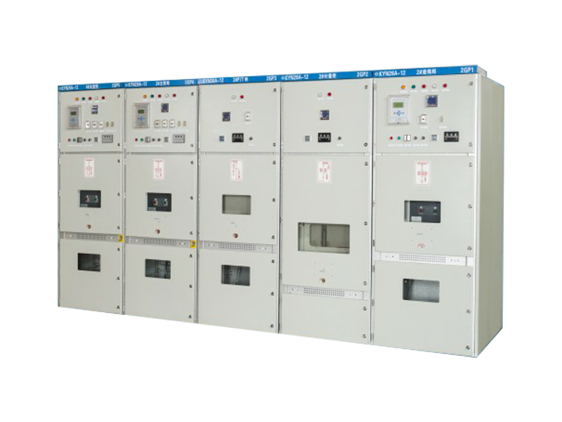
Medium Voltage Switchgear
View Details →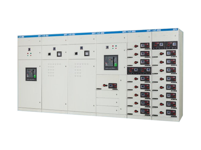
Low Voltage Panel AT-GCK1
View Details →